
Distributor Ignition Systems
The distributor is the heart of the ignition system. Its three basic functions are to trigger the firing of the ignition coil, to control timing advance, and to route or distribute the coil's high voltage output to the individual spark plugs.
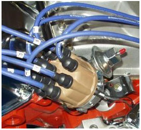
Fig 1. Distributor Ignition Systems
On older applications with breaker point ignition systems, the contact points switch the ignition coil's primary voltage on and off. The points are mounted on a movable plate in the distributor housing. Cam lobes on the distributor shaft rotate against a plastic block on the points to open and close the points. On newer applications with electronic ignition systems, the distributor contains a magnetic pickup or Hall effect switch instead of points to generate a signal for the ignition module (which switches the coil on and off). On many applications, the ignition module itself is also located inside the distributor (GM HEI) or mounted on the distributor housing (Ford TFI).
DISTRIBUTOR WEAR
Wear in the distributor drive gear can introduce play that can retard timing, while worn distributor shaft bushings (often the result of infrequent oil changes and varnish buildup on the shaft) can result in erratic timing. Both conditions can affect engine performance, fuel economy and emissions. If the distributor is worn, replacement is the only repair option.
SPARK ADVANCE
With respect to timing, the distributor on older applications has both a centrifugal advance mechanism and vacuum advance diaphragm. Flyweights and springs in the centrifugal advance mechanism add timing advance as engine speed increases. Bushing wear, rust, or weak or broken springs may cause the centrifugal advance mechanism to overadvance or retard timing. Lubricating the mechanism with high temperature dielectric grease and/or replacing weak or broken springs may solve a sticking problem, but worn bushings call for distributor replacement.
The vacuum advance diaphragm rotates the breaker plate to advance timing when intake vacuum is high to improve fuel economy, and retards timing when the engine is under heavy load to prevent detonation (spark knock). If the diaphragm can't hold vacuum, the diaphragm must be replaced (if available separately).
DISTRIBUTOR ROTOR & CAP
The distributor rotor directs the ignition coil's high voltage output to the various spark plug terminals in the distributor cap. The condition of the cap and rotor are very important, as is the "air gap" or distance between the tip of the rotor and cap terminals. If the cap or rotor are cracked, worn, eroded or have carbon tracks, either or both should be replaced.
Sometimes a distributor will "eat" caps. Often this is due to excessive end play in the distributor shaft. Too much end play allows the rotor to push up against the cap and wear down the center button. The rotor may even contact the terminals and damage or break the cap. Shimming the distributor shaft may reduce the end play, but replacement may also be necessary.
REPLACING A DISTRIBUTOR
If your engine needs a distributor, buying a remanufactured unit can usually save you money compared to buying a new one.
A used distributor from a low mileage vehicle in a salvage yard should be okay, but you may have to buy a new cap and rotor for it. Watch out for used distributors at swap meets because they may have been modified for a performance engine and will have the wrong spark advance curves for a stock engine.
Older breaker point distributors usually come complete with new points, condenser, rotor and cap. The points are usually preadjusted so the unit can be dropped right in and the timing set. Some of the newer electronic distributors come complete with a module, rotor and cap while others do not.
One very important point to note when installing GM HEI and Ford TFI ignition module in or on a distributor is to apply a coating of dielectric grease to the underside of the module. Grease is needed to conduct heat away from the module. Forget the grease and the module will likely fail within a few thousand miles.
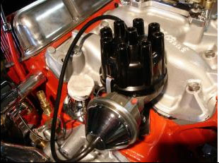
Fig 2. Replacing a distributor
The index position of the distributor is very important because it must be aligned correctly with the camshaft for proper ignition timing. Before you remove the old distributor, rotate the engine until the #1 piston is at top dead center (use the timing marks on the crankshaft pulley). Remove the cap and see if the rotor is lined up with the cap terminal for the #1 piston. If it is not, rotate the crankshaft 180 degrees so it is lined up with the #1 spark plug terminal. Then remove the distributor hold down nut and clamp, note where the vacuum advance is pointing, then pull the distributor out of the engine.
When you install the new distributor, line up the vacuum advance in the same direction as the old distributor was pointing, rotate the shaft so the rotor will be pointing approximately in the same location as the #1 spark plug terminal, then slide the distributor into the engine. The angle of the drive gears will cause the rotor to rotate slightly and the distributor slides all the way into the engine. Replace the distributor hold down clamp and nut, but do not tighten.
Start the engine and use a timing light to adjust the timing to specifications (typically 6 to 10 degrees of advance with the vacuum advance hose disconnected and plugged at 550 to 650 rpm idle speed). Refer to the emissions decal under the hood, a service manual or online service information for the timing specifications and procedure for your engine, because they do vary quite a bit. If the engine has computer controlled spark timing, no adjustment is possible. Just lock down the distributor.
Distributorless Ignition Systems (DIS)
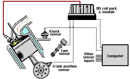
Fig 3. Distributorless Ignition Systems (DIS)
Distributorless ignition systems (DIS) have been around for almost a decade now, and have eliminated much of the maintenance that used to be associated with the ignition system. No distributor means there is no distributor cap or rotor to replace, and no troublesome vacuum or mechanical advance mechanisms to cause timing problems. Consequently, DIS ignition systems are pretty reliable.
Even so, that does not mean they are trouble-free. Failures can and do occur for a variety of reasons. So knowing how to identify and diagnose common DIS problems can save you a lot of guesswork the next time you encounter an engine that cranks but refuses to start, or one that runs but is missing or misfiring on one or more cylinders.
If an engine cranks but will not start, is it fuel, ignition or compression? Ignition is usually the easiest of the three to check because on most engines, all you have to do is pull off a plug wire and check for spark when the engine is cranked. On coil-over-plug DIS systems, there are no plug wires so you have to remove a coil and use a plug wire or adapter to check for a spark.
If there is no spark in one cylinder, try another. No spark in any cylinder would most likely indicate a failed DIS module or crankshaft position (CKP) sensor. Many engines that are equipped with electronic fuel injection also use the crankshaft position sensor signal to trigger the fuel injectors. So, if there is no spark and no injector activity, the problem is likely in the crank position sensor. No spark in only one cylinder or two cylinders that share a coil would tell you a coil has probably failed.
DIS COIL CHECKS
The coils in DIS ignition systems function the same as those in ordinary ignition systems, so testing is essentially the same. But the driveability symptoms caused by a weak coil or dead coil will be limited to one or two cylinders rather than all the cylinders. Many DIS systems use the "waste spark" setup where one coil fires a pair of spark plugs that are opposite one another in the firing order. Others, including the newer coil-over-plug systems, have a separate coil for each spark plug.
Individual DIS coils are tested in essentially the same way as epoxy-filled (square-type) ignition coils. First, isolate the coil pack by disconnecting all the leads. Set the ohmmeter in the low range, and recalibrate if necessary. Connect the ohmmeter leads across the ignition coil primary terminals, and compare the primary resistance reading to specifications (typically less than 2 ohms). Then connect the ohmmeter leads across the coil secondary terminals and compare the secondary resistance reading to specifications (typically 6,000-30,000 ohms). If readings are outside the specified range, the coil is defective and needs to be replaced.
If measuring the secondary resistance of a DIS coil is difficult because of the coils location, try removing the wires from the spark plugs and measure secondary resistance through the plug wires rather than at the secondary terminals on the coils. Just remember to add in a maximum of 8,000 ohms of resistance per foot for the plug wires.
DIS MODULE & SENSOR CHECKS
Here is a little trick that will literally show you if a DIS module and its crankshaft sensor circuit are working: connect a halogen headlamp to the spade terminals that mate the DIS module to the coils. A headlamp is recommended here because it puts more of a load on the module than a test lamp. If the headlamp flashes when the engine is cranked, the DIS module and crankshaft position sensor circuit are functioning. Therefore, the problem is in the coils.
If the headlamp does not flash, or there is no voltage to the module or coil pack when the engine is cranked, the problem is most likely in the crankshaft sensor circuit. On most vehicles, a bad crank position sensor will usually set a fault code, so use a scan tool to check for a code. Or, check the crank sensor itself.
Magnetic crank sensors can be tested by unplugging the electrical connector and checking resistance between the appropriate terminals. If resistance is not within specs, the sensor is bad and needs to be replaced.
Magnetic crank position sensors produce an alternating current when the engine is cranked so a voltage output check is another test that can be performed. With the sensor connected, read the output voltage across the appropriate module terminals while cranking the engine. If you see at least 20 mV on the AC scale, the sensor is good, meaning the fault is probably in the module. If the output voltage is low, remove the sensor and inspect the end of it for rust or debris (magnetic sensors will attract iron and steel particles). Clean the sensor, reinstall it and test again. Make sure it has the proper air gap (if adjustable) because the spacing between the end of the sensor and the reluctor wheel or notches in the crankshaft will affect sensor output voltage. If the air gap is correct and output is still low, replace the sensor.
Hall effect crankshaft position sensors typically have three terminals; one for current feed, one for ground and one for the output signal. The sensor must have voltage and ground to produce a signal, so check these terminals first with an analog voltmeter. Sensor output can be checked by unplugging the DIS module and cranking the engine to see if the sensor produces a voltage signal. The voltmeter needle should jump each time a shutter blade passes through the Hall effect switch. If observed on an oscilloscope, you should see a square waveform. No signal would tell you the sensor has failed.
DIS PERFORMANCE PROBLEMS
In instances where the engine starts and runs but does not perform well (lack of power, poor fuel economy, spark knock, elevated emissions, etc.), the problem may be outside the DIS system. First, the individual coils should be tested to make sure their primary and secondary resistance is within specs. If the coils are all okay, the electronic spark control circuit may be receiving bad information from another sensor.
Low MAP sensor output voltage or a coolant sensor that reads cold all the time will allow more spark advance than normal. This, in turn, may cause detonation (spark knock) problems when the engine is under load. So too can a faulty knock sensor or an EGR valve that is not working.
High MAP output voltage or a misadjusted throttle position sensor can have the opposite effect and cause the spark control system to retard timing more than normal. Retarded timing will reduce performance and fuel economy.
Do not forget, too, that ordinary secondary ignition problems can also cause misfires with DIS the same as a conventional ignition system. A bad spark plug wire or a worn or fouled spark plug will act just like a weak or bad DIS coil. So anytime you find an ignition problem that is isolated to a single cylinder, remove and inspect the spark plug and plug wire to rule out those possibilities.
For more information on vehicle electrical systems, please check out the lots more information in RIBO Parts Articles. 


